
Evaluate Insulation Integrity with Insulation Resistance Testing
Evaluate Insulation Integrity with Insulation Resistance Testing
Cable Insulation offers a protective layer to wires and cable. As a non-conductive latter, insulation resists electrical leakage and prevents cable conductors from contact with other conductors and other external threats such as heat, water, and chemicals.
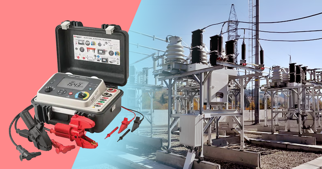
Insulation resistance testing of wires and cables is significant in evaluating insulation integrity, electrical safety, and conductivity. Insulation resistance testing methods like Megger help determine insulation quality and resistance to current flow and detect any insulation damage.
Gloster Cable wires and cables pass through insulation resistance testing to ensure cable safety and longevity.
Insulation Resistance Testing and Its Purpose
The insulation resistance test helps measure the resistance between two points separated through electrical insulation. It helps determine dielectric or insulation effectiveness in restricting the electric current flow. Insulation resistance testing applies a test voltage to determine how effective the insulation is in preventing the flow of electric current out of the insulation. It is similar to pumping pressurized water in a water pipe to identify leaks.
Insulation resistance testing of wires and cables helps verify insulation quality during the manufacturing stage, installation period, and their use over time.
Purpose of Insulation Testinge
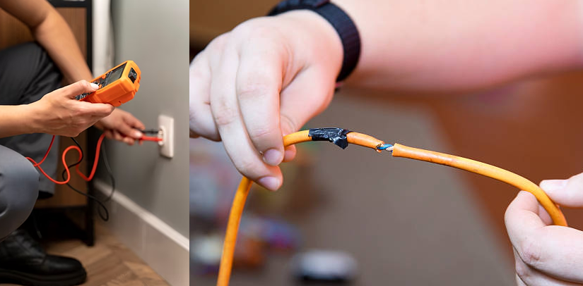
Insulation starts to age from the time it gets manufactured. When an electric current passes through a conducting wire, there is a current loss along the way. Then, insulation testing helps verify if there is any current leakage.
Insulation testing helps verify the cable or wire’s reliability and identify if the cable is in good working condition. It is essential to avoid any injury and damage. We can find cable insulation service life and longevity of cable insulation with insulation resistance testing.
The Principal of Insulation Resistance Test
The insulation resistance principle is R=V/I. It says to apply the voltage to measure the steady- state leakage current and then divide the voltage by the current. We can calculate the measurement’s target insulation resistance by measuring the current low to the target once the voltage ‘V’ applies. And then divide V with the resulting current. IR test is successful if R meets the necessary value.
The IR test needs an IR tester, a portable ohmmeter with a built-in generator that produces a high DC voltage. The DC voltage usually measures 500V and causes a current to flow around the surface of the insulation. The resistance reading measures leakage current- a high IR reading means less current is escaping through the insulation, and a low IR reading indicates strong-current leakage and may indicate a break in the insulation.
Methods Used for Insulation Resistance Test
We can measure the Insulation resistance test using an instrument called a megger. The instrument is power-driven through an in-built DC generator or higher voltage battery. Megger is also known as Megohmmeter.
Meg Test and Components for Insulation Resistance Testing
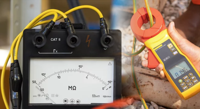
 Megohmmeter
A megohmmeter is similar to a multimeter when it is in its ohmmeter function. However, a
megohmmeter’s output is much higher than a multimeter. The voltage range application for the
instrument is 100, 250, 500, 1000, 2500, 5000, and even 10,000V. The most common are 500V
and 1000V. Higher voltages are for stress insulation to a greater degree and obtain more
accurate results.
Megohmmeters have a high internal resistance, making the instrument less hazardous for high-
voltage applications.
Testing Connection
A megohmmeter consists of three terminals- the line terminal(L), earth terminal(E), and guard
terminal(G). The L terminal is called the hot terminal and connects to the conductor whose
insulation resistance we measure. E terminal connects to the other side of the insulation, the
ground conductor. The G terminal provides a return circuit that bypasses the meter.
Various Insulation Resistance Test
The types of insulation resistance tests we can perform by a mega-ohm-meter are as follows.
Short-Time or Spot Reading Test
Connect the megger device across the insulation for performing a short-time reading test. We can perform the test for 60 seconds. We must consider factors like humidity, temperature, and insulation conditions as they can affect the meter reading.
Time-Resistance Test
The time resistance test method depends on a good insulation absorption effect in comparison to contaminated insulation. The megger device will take readings at exact times and note the differences. It shows an increase in resistance over a certain period if the insulation is fine. The test provides conclusive data with no record from earlier tests.
Dielectric Absorption Ratio
Dielectric absorption ratio is the ratio of two-times resistance readings and is very useful in recording insulation information. For example, we can divide a one-minute reading by 30 30-second reading with a megger device. The test assumes that good insulation will show- gradually increasing IR after applying the test voltage.
Step-Voltage Test
Step voltage test evaluates aged or damaged insulation. We need a dual voltage test instrument, and after the connections, the IR testing should be at low voltage, 500V. Discharge the test specimen and perform it again at a higher voltage of 2500V. If there is more than a 25% difference in both readings, there are chances of insulation damage or deterioration.
Advantage of Conducting Insulation Resistance Test of Wires and Cables
The advantages of performing the test at regular intervals bring the following advantages.
Verifies Insulation Quality
A high level of resistance means very little current escaping through the insulation. The insulation resistance test determines how effective the dielectric insulation resists the flow of electric current.
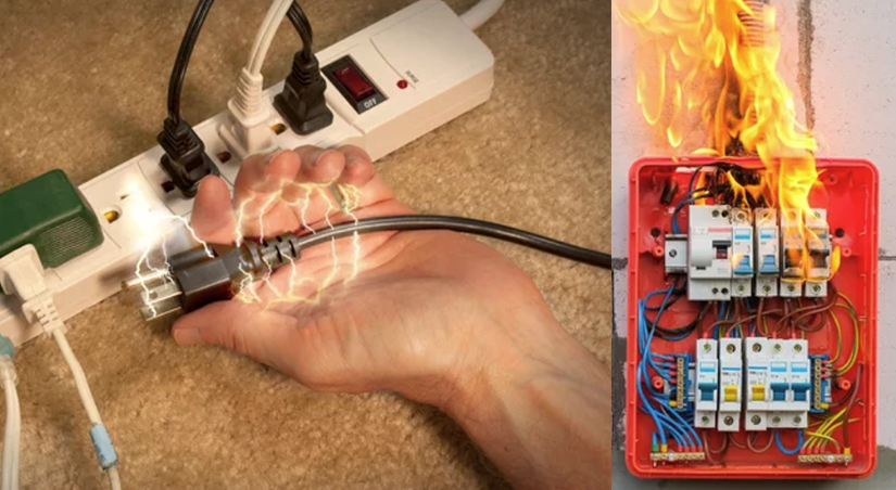
Avoid Electrical Shocks
The test helps avoid hazards like short circuits and electric shocks caused by insulation deterioration during wires and cables utilized in buildings and industrial parts.
Measures Resistance and Its Effectiveness
Insulation resistance test helps determine resistance between any two points separated through Electrical Insulation. It also finds the resistance effectiveness while restricting the current flow.
Quality Control Measure
The insulation resistance test is a quality control measure used during the manufacturing of wires and cables. It evaluates the insulation's durability and effectiveness.
Maintain Insulation Integrity to Avoid Any Electrical Mishap
Insulation integrity is essential in maintaining insulation quality, performance, and durability. Gloster Cables, a wire and cable manufacturer, performs insulation resistance as its quality control measure to offer quality products. IR test at Gloster adheres to several international standards depending on cable insulation material and type to get the optimum results.
CONTACT US